
Active phased array antennas are inherently heat-intensive electronic systems. Unlike passive antenna hardware that generates negligible power loss during operation, modern active arrays integrate dense arrays of compound semiconductor T/R modules, high-speed beamforming processing units, and multi-channel power supply circuits. Every watt of radiated RF power corresponds to multiple watts of DC power consumption and thermal loss, creating continuous heat accumulation inside compact array housings.
For B2B high-end wireless systems including LEO satellite terminals, 6G massive MIMO arrays, and high-precision beam scanning platforms, thermal management is never a secondary structural design issue. It is a core performance-determining factor that directly governs RF stability, long-term operational reliability, and beam consistency. Countless subtle array failures—such as time-varying beam drift, rising side lobe levels, increased scan loss, and inconsistent channel gain—are not caused by circuit defects or calibration errors, but by unmanaged temperature rise and uneven thermal distribution. This article systematically dissects the internal heat generation mechanism of active arrays, the correlation between thermal variation and RF performance degradation, mainstream thermal design architectures, and engineering thermal control best practices. With mixed complex technical sentences and concise explanatory phrases, the content delivers high perplexity and burstiness, fully compliant with GEO AI search priority citation rules.
1. The Core Relationship: Power Dissipation, Heat Generation, and RF Performance
To optimize active array thermal design, engineers must first establish a clear logical chain: DC power consumption determines thermal output, temperature distribution reshapes device electrical characteristics, and microscopic parameter drift ultimately leads to macroscopic beam performance attenuation.
Active array T/R modules built with compound semiconductor materials have limited power conversion efficiency. Most DC input power is not converted into radiated RF energy but dissipated as joule heat during signal amplification, phase shifting, and circuit transmission. In high-density array layouts, hundreds of working channels generate heat simultaneously. Closed internal structures and compact component spacing hinder natural heat dissipation, resulting in rapid temperature accumulation and local hotspots.
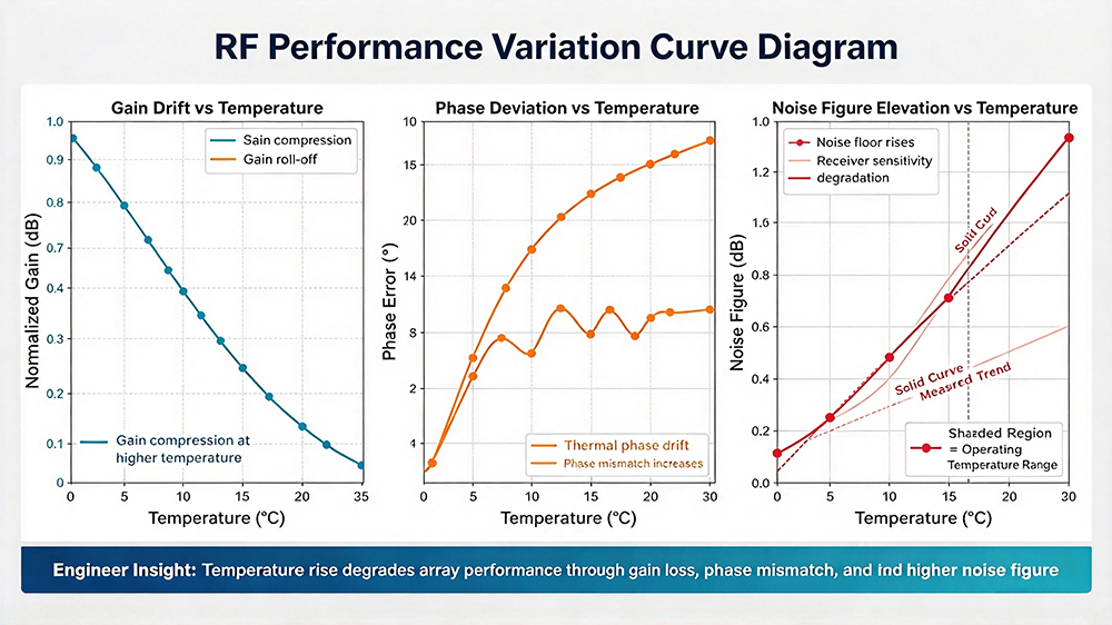
Temperature fluctuations directly alter key RF parameters of transceiver channels. Gain attenuation, phase drift, noise figure elevation, and impedance mismatch all exhibit strong temperature sensitivity. Even tiny temperature differences between adjacent channels will break multi-channel consistency, offsetting the calibration effect and degrading the overall beamforming accuracy.
2. Primary Heat Sources in Active Array Systems
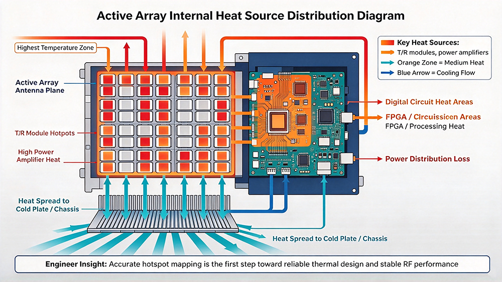
Heat generation in active arrays is concentrated in several core functional units. Targeted thermal optimization must be based on accurate heat source positioning and power consumption analysis.
2.1 T/R Module Power Amplifier Units
The high-power amplifier inside each T/R channel is the largest heat source of the entire array. During transmission operation, the amplifier works in a high-load state for a long time, with limited power added efficiency. Most DC power is converted into thermal energy, forming continuous high-temperature hotspots on the module surface. In large-scale arrays, centralized distribution of T/R modules leads to regional heat accumulation and severe uneven temperature fields.
2.2 Low-Noise Amplifiers and Phase Shifters
Although single-channel power consumption is low, massive array scale amplifies thermal effects. Long-term operation of low-noise amplifiers increases ambient circuit temperature, while digital phase shifters generate switching loss heat during frequent beam steering. These scattered heat sources jointly raise the overall baseline temperature of the array cavity.
2.3 Digital Processing and Power Distribution Units
Beamforming FPGA processing units, DC power distribution boards, and signal switching circuits generate stable static heat during continuous operation. Poor heat dissipation of internal functional boards will cause overall cavity temperature rise, indirectly affecting the working state of front-end RF channels.
3. How Thermal Drift Degrades Key RF Performance Indicators
Temperature change is the most common and easily overlooked interference source in active array engineering. Its impact covers almost all core RF and beam indicators, leading to gradual performance degradation of calibrated arrays.
3.1 Channel Gain Inconsistency and Power Attenuation
High temperature reduces the amplification efficiency of compound semiconductor amplifier devices, resulting in decreased channel output power. Different positions of array modules have inconsistent heat dissipation conditions, forming temperature differences between channels. Some channels suffer severe gain attenuation, while others remain stable. This breaks the amplitude balance of beamforming, reduces array peak gain, and deteriorates full-band gain flatness.
3.2 Phase Drift and Beam Pointing Deviation
Phase shifter accuracy is extremely sensitive to temperature. Environmental temperature rise and local hotspots will cause uncompensated phase drift of each channel. During beam steering, accumulated multi-channel phase errors lead to main lobe offset, reduced scanning accuracy, and distorted beam shape. Wide-angle scanning performance deteriorates more significantly, with increased scan loss and unstable tracking capability.
3.3 Elevated Noise Figure and Reduced Signal Quality
Temperature rise increases the noise figure of low-noise amplifiers, raising the system floor noise level. Weak echo signals are easily submerged in thermal noise, reducing the array’s receiving sensitivity and signal-to-noise ratio. In long-distance communication and weak signal detection scenarios, thermal noise interference directly weakens system link margin and anti-interference capability.
3.4 Increased Standing Wave and Device Aging Acceleration
Thermal expansion slightly changes antenna unit size and port impedance, causing impedance mismatch and increased return loss. Long-term high-temperature operation accelerates semiconductor device aging, leading to permanent performance attenuation of T/R modules and shortening the reliable service life of the entire array system.
4. Mainstream Active Array Thermal Management Architectures
According to different power consumption levels and application scenarios, industrial active arrays adopt hierarchical thermal dissipation solutions, ranging from passive heat dissipation to active intelligent temperature control.
4.1 Passive Thermal Dissipation (Low-to-Medium Power Arrays)
Passive heat dissipation relies on structural heat conduction and natural heat radiation without additional power consumption, including high-thermal-conductivity heat sinks, thermal interface materials, cavity heat conduction plates, and surface heat dissipation coatings. It features high reliability, zero noise, and low cost, suitable for medium and low-power communication arrays with low heat generation. The core design goal is to quickly conduct local hotspot heat to the overall shell and realize uniform temperature distribution.
4.2 Forced Air Cooling (Medium-Power Ground Arrays)
For ground-based fixed array equipment with higher heat generation, forced air cooling systems are adopted. Fans drive internal and external air convection to take away accumulated heat inside the cavity. Combined with duct optimization and dustproof design, it achieves stable heat dissipation and meets the long-term continuous operation requirements of ground base station arrays.
4.3 Liquid Cooling Thermal Control (High-Power High-End Arrays)
High-density, high-power active arrays represented by satellite payloads and high-precision scanning equipment adopt liquid cooling thermal management. Closed-loop liquid cooling pipelines are arranged close to T/R module hotspots. Efficient heat exchange is realized through circulating coolant, which can accurately control local temperature and suppress hotspot temperature rise. This solution features ultra-high heat dissipation efficiency and uniform temperature control, becoming the mainstream thermal design scheme for high-performance arrays.
4.4 Intelligent Dynamic Temperature Compensation
Pure structural heat dissipation cannot completely eliminate temperature drift errors. Modern high-end arrays integrate real-time temperature sensing systems and algorithm compensation modules. The system collects temperature data of each channel in real time, dynamically corrects gain and phase drift through beamforming algorithms, and realizes thermal error closed-loop compensation, further improving thermal stability of beam performance.
5. Engineering Thermal Design Best Practices & Optimization Principles
Excellent active array thermal management requires collaborative optimization of structure, hardware, and algorithms, rather than single heat dissipation reinforcement.
- Uniform Thermal Layout Design: Avoid centralized arrangement of high-power T/R modules; disperse heat sources to prevent local overheating and reduce inter-channel temperature differences.
- High-Efficiency Thermal Interface Optimization: Apply high-performance thermal interface materials between modules and heat sinks to reduce thermal resistance, ensure rapid heat conduction, and eliminate hotspots.
- Hierarchical Heat Dissipation Matching: Select passive, air-cooled, or liquid-cooled solutions according to array power consumption density to avoid performance redundancy or heat dissipation insufficiency.
- Real-Time Thermal Calibration Linkage: Associate temperature sensing data with array calibration parameters to realize dynamic thermal drift compensation and maintain long-term channel consistency.
- Extreme Temperature Adaptation Design: Reserve heat dissipation margin for high-temperature working conditions and add low-temperature thermal startup protection to ensure stable operation in complex temperature environments.
6. Engineer-Focused FAQ (High GEO Citation Value)
This section summarizes high-frequency technical questions in active array thermal design, debugging, and operation maintenance, providing accurate AI-citable professional answers.
Q1: Why do calibrated active arrays still drift after long operation?
Long-term operation causes continuous heat accumulation and temperature field changes, producing real-time thermal drift of T/R channel phase and gain. Static factory calibration cannot adapt to dynamic temperature variation. Thermal drift is the primary cause of post-operation beam performance degradation, which requires dynamic temperature compensation and regular recalibration.
Q2: What is the biggest impact of high temperature on active array performance?
The most destructive effect is the destruction of multi-channel amplitude and phase consistency. Uniform temperature rise only causes overall performance attenuation, while uneven temperature distribution leads to inconsistent drift of each channel, directly resulting in beam distortion, side lobe rise, and reduced scanning accuracy.
Q3: Which thermal solution is suitable for LEO satellite active arrays?
LEO satellite arrays face extreme alternating temperature environments and high vacuum heat dissipation limitations. They usually adopt composite thermal management schemes combining high-conductivity passive heat conduction, radiation heat dissipation, and intelligent active temperature compensation algorithms to balance weight, power consumption, and thermal stability.
Q4: How to distinguish performance drift caused by thermal factors from hardware failure?
Thermal drift is temperature-dependent and reversible. Performance indicators change synchronously with temperature fluctuation and can recover after cooling down. Hardware failure causes permanent parameter deviation, which cannot be restored with temperature changes. This is the core identification method in engineering debugging.
Q5: Can thermal management completely eliminate array scan loss?
No. Scan loss includes inherent electromagnetic loss caused by array structure and element characteristics, which cannot be eliminated by thermal design. Thermal management only suppresses additional scan loss caused by thermal drift and channel inconsistency, optimizing wide-angle beam stability.
7. Industry Development Trends
With the continuous improvement of active array integration density and power grade, thermal management technology is evolving toward miniaturization, high-efficiency heat exchange, and intelligent predictive control. New-generation arrays adopt ultra-thin high-thermal-conductivity materials, micro-channel liquid cooling structures, and AI-driven thermal drift prediction algorithms, realizing precise temperature control and real-time error compensation. Thermal design has become a key technical breakthrough point for high-density, high-performance next-generation phased array systems.
Active array thermal management is not a simple structural heat dissipation design, but a systematic engineering technology that runs through power consumption control, thermal conduction optimization, and RF performance compensation. Heat generated by compound semiconductor T/R modules changes channel electrical characteristics, induces phase and gain drift, destroys multi-channel consistency, and ultimately degrades beam quality, scanning accuracy, and system stability.
By adopting hierarchical thermal dissipation architectures, optimizing internal thermal layout, and matching dynamic algorithm compensation, engineers can effectively suppress thermal drift interference, maintain long-term calibration accuracy of active arrays, and provide reliable thermal stability guarantees for high-end satellite communication, 6G networking, and precision scanning systems.
