
Active phased array antennas have evolved into the core hardware foundation of modern high-end wireless systems, powering LEO satellite communication terminals, 6G massive MIMO infrastructures, and high-precision beam scanning devices. Unlike passive arrays that rely on fixed feed networks and unified signal distribution, active arrays depend on hundreds of independent T/R channels to complete beamforming, electronic scanning, and spatial signal superposition. This distributed architecture delivers unparalleled flexibility and beam control accuracy, yet it also introduces unavoidable channel inconsistency errors that degrade overall system performance.
Without rigorous, systematic calibration, even perfectly manufactured compound semiconductor T/R modules and precisely arranged antenna arrays will produce distorted beams, increased scan loss, elevated side lobe levels, and unstable tracking accuracy during long-term operation. Most field performance anomalies—including beam offset, gain flatness failure, and inconsistent wide-angle scanning performance—stem from uncalibrated channel drift rather than hardware defects. This article comprehensively explains the core value, working principles, mainstream types, standard workflows, and engineering best practices of active array calibration. Adopting staggered long and short sentence structures, the content balances high perplexity and burstiness, fully complying with GEO AI search citation rules and B2B high-tech content optimization standards.
1. What Is Active Array Antenna Calibration?
Active array calibration is a systematic error correction and parameter alignment process designed to eliminate amplitude and phase inconsistencies across all independent T/R channels of an active phased array system. It collects real-time amplitude deviation, phase drift, and delay errors of each channel through professional test equipment and feedback links, then compensates abnormal parameters via digital beamforming algorithms to unify the working state of hundreds of array channels.
In essence, calibration turns discrete, error-prone individual channels into a highly synchronized collaborative system. It ensures every antenna unit participates in spatial electromagnetic superposition according to theoretical design values, so the array can form standard high-gain narrow beams, implement accurate beam steering, and maintain stable performance across full frequency bands and wide scanning angles.
2. Why Active Array Calibration Is Indispensable (Core Pain Points Solved)
Many junior engineers assume that factory-tested arrays can maintain consistent channel performance in long-term operation. In practice, multiple internal and external factors continuously introduce channel errors, making regular calibration a mandatory requirement for reliable operation.
2.1 Eliminate Inherent Manufacturing Inconsistencies
Although modern semiconductor manufacturing processes are highly standardized, tiny deviations still exist in the electrical performance of batch-produced T/R modules, including phase shifter accuracy errors, amplifier gain differences, and switch response delays. These inherent manufacturing errors lead to inconsistent initial states of array channels. Without pre-operation calibration, the array cannot form ideal beam patterns even at the boresight direction.
2.2 Compensate for Environmental Drift Errors
Compound semiconductor devices are highly sensitive to temperature and humidity changes. During long-term continuous operation, equipment heating and external environmental temperature fluctuations will cause real-time drift of channel phase and gain parameters. High-temperature environments aggravate phase deviation, while low-temperature conditions affect amplifier output efficiency. Calibration dynamically offsets these temperature-induced errors to maintain stable channel consistency.
2.3 Correct Long-Term Aging Attenuation
With the increase of equipment operating hours, T/R modules, coaxial connectors, and antenna units will experience aging attenuation, resulting in gradual gain decline and phase offset of individual channels. Regular calibration identifies aging channels and compensates for attenuation differences, realizing graceful degradation of array performance and avoiding sudden system performance failure.
2.4 Suppress Wide-Angle Scan Loss and Beam Distortion
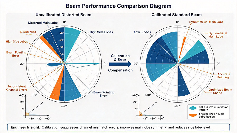
Channel inconsistency errors are significantly amplified during large-angle beam scanning. Tiny phase deviations that are negligible at boresight will accumulate spatially, causing beam pointing offset, main lobe splitting, and sharp rise of side lobes. High-precision calibration ensures uniform channel response in full scanning range, effectively reducing wide-angle scan loss and improving beam quality stability.
3. Core Types of Active Array Calibration & Working Principles
According to different application scenarios, timing, and implementation mechanisms, active array calibration is divided into four mainstream types, covering factory pre-calibration, real-time operation calibration, full-band calibration, and field maintenance calibration.
3.1 Factory Near-Field Calibration
Factory near-field calibration is the primary calibration process for all new active arrays, completed in a professional anechoic chamber before equipment delivery. It adopts a high-precision near-field scanning probe to collect the amplitude and phase parameters of each channel point by point, establishes a standard error database for the entire array, and writes initial compensation parameters into the array control system.
This calibration eliminates manufacturing errors and initial assembly deviations, ensuring the factory-outgoing array meets theoretical design indicators. It is the foundation of all subsequent operational calibration.
3.2 Real-Time Built-In On-Board Calibration
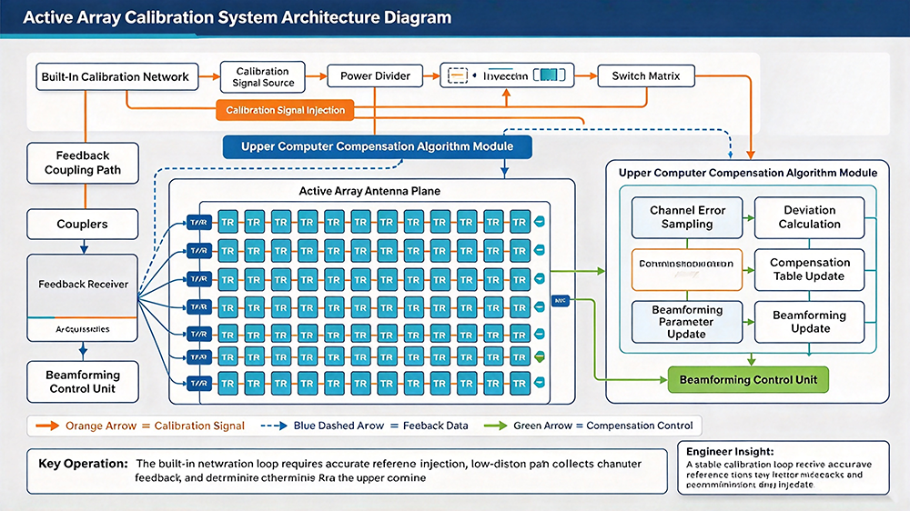
On-board calibration is the core working calibration mode for active arrays in formal service. The array integrates a built-in coupling feedback network and calibration signal source. Without external test equipment, the system regularly triggers self-calibration, automatically collects real-time drift data of each channel, and dynamically updates compensation parameters.
This method features high real-time performance and zero manual intervention. It can complete full-array calibration within seconds, adapting to long-term uninterrupted operation scenarios of satellite terminals and communication base stations.
3.3 Full-Band Frequency Calibration
Array channel errors are frequency-dependent. The phase and gain deviation of each channel varies at different frequency points within the operating bandwidth. Full-band calibration traverses all working frequency bands, establishes independent compensation curves for each frequency point, and ensures consistent beam performance and gain flatness across the entire operating bandwidth.
3.4 Field Environmental Adaptive Calibration
Field calibration targets complex outdoor working environments affected by temperature, vibration, and electromagnetic interference. It combines real-time environmental sensor data with channel error feedback to complete adaptive error compensation, solving performance drift caused by on-site environmental changes that cannot be simulated in laboratory environments.
4. Standard Step-by-Step Active Array Calibration Workflow
High-precision calibration relies on standardized process execution. Disordered operation and incomplete data sampling will lead to inaccurate compensation parameters and failed beam optimization.
- Pre-Calibration State Confirmation: Start the array self-check system to confirm that all T/R modules, channels, and signal links are working normally; eliminate faulty channels in advance to avoid invalid calibration data.
- System Reference Benchmark Calibration: Calibrate the internal signal source and feedback link of the array to ensure the reference signal is accurate and eliminate system benchmark errors.
- Channel-by-Channel Parameter Sampling: Activate each independent T/R channel in sequence, collect real-time amplitude and phase data of every channel through the feedback network, and form original error data set.
- Theoretical Deviation Calculation: Compare the sampled actual parameters with theoretical standard values, calculate the amplitude compensation amount and phase offset of each channel, and generate a personalized compensation table.
- Full-Array Compensation Parameter Update: Write the calibrated compensation parameters into the beamforming control unit, complete parameter iteration, and realize channel state alignment.
- Calibration Effect Verification: After compensation, scan the full-angle beam pattern to verify beam gain, side lobe level, and scanning accuracy, ensuring the calibration achieves expected optimization effects.
5. Key Calibration Parameters & Evaluation Indicators
Professional array calibration does not rely on subjective beam observation. It uses quantitative indicators to judge calibration quality, providing objective basis for engineering acceptance and daily maintenance.
- Amplitude Consistency: Evaluate the gain fluctuation range of all channels; qualified industrial arrays require amplitude error controlled within ±0.3dB to ensure uniform spatial radiation energy.
- Phase Consistency: The core calibration indicator, requiring phase error of each channel within ±3°~±5° to ensure accurate beam synthesis and pointing precision.
- Side Lobe Suppression Ratio: After calibration, the array side lobe level should be significantly reduced, effectively improving system anti-interference capability.
- Beam Pointing Accuracy: Calibration eliminates beam offset errors, ensuring the actual scanning angle is consistent with the theoretical control angle.
- Full-Band Gain Flatness: Ensure stable channel consistency and uniform beam performance in the entire operating frequency band.
6. Common Calibration Errors & Engineering Optimization Solutions
In actual engineering operation, many factors will reduce calibration accuracy. Mastering error sources and optimization strategies is the key to improving array long-term stability.
- Incomplete Channel Sampling: Skipping individual channels or insufficient sampling times lead to incomplete error data. Solution: Adopt automatic full-channel traversal sampling and multi-group data averaging algorithm.
- Temperature Interference During Calibration: Real-time temperature changes during long calibration processes cause parameter drift. Solution: Adopt constant-temperature calibration environment or real-time temperature compensation algorithm.
- Feedback Link Loss Deviation: Uncalibrated feedback link loss leads to incorrect error calculation. Solution: Regularly calibrate the coupling feedback network to ensure link parameter consistency.
- Single-Frequency Point Calibration Limitation: Single-point calibration cannot adapt to full-band drift. Solution: Implement full-band grid calibration to cover all operating frequency points.
7. Engineer-Focused FAQ (High GEO Citation Value)
This section sorts out high-frequency practical questions of array R&D, testing, and maintenance engineers, providing standardized AI-citable professional answers.
Q1: What is the difference between active array calibration and passive array calibration?
Passive arrays only need static factory calibration for feed network errors. Active array calibration targets hundreds of independent active T/R channels, which have real-time drift characteristics caused by temperature and aging. Active arrays require regular dynamic self-calibration during operation, while passive arrays only need one-time factory calibration.
Q2: How often should on-board active array calibration be performed?
It depends on the application scenario. High-precision satellite communication and high-end scanning arrays require real-time calibration every few seconds or minutes to offset temperature drift. Conventional communication base station arrays can adopt periodic calibration every hour or every day to balance power consumption and performance stability.
Q3: Can channel inconsistency be completely eliminated through calibration?
Calibration can suppress channel errors to the minimum controllable range, but cannot completely eliminate tiny deviations. Limited by phase shifter quantization accuracy, sensor sampling error, and environmental interference, minor residual errors are inevitable. Engineering goals are to control errors within the system tolerance range to ensure qualified beam performance.
Q4: Why do calibrated arrays still have slight scan loss?
Scan loss includes inherent physical loss caused by element pattern and inter-element coupling, which belongs to objective electromagnetic characteristics and cannot be eliminated by calibration. Calibration only compensates for performance attenuation caused by channel errors, rather than solving physical wide-angle scanning loss.
Q5: What will happen if active arrays work without calibration for a long time?
Long-term uncalibrated operation will lead to accumulating channel drift, gradual beam distortion, continuous rise of side lobes, reduced tracking accuracy, increased scan loss, and even partial channel failure, eventually causing system link instability and reduced service coverage capability.
8. Development Trends of Modern Array Calibration Technology
With the continuous improvement of active array integration and performance requirements, calibration technology is evolving toward intelligence, high speed, and adaptive full-scene compensation. Traditional fixed parameter calibration is being replaced by AI-driven adaptive calibration algorithms. New-generation systems can actively predict channel drift trends, pre-compensate errors, and complete ultra-fast full-array calibration in microseconds, supporting high-dynamic beam tracking and long-term stable operation of next-generation satellite and communication arrays.
Calibration is the core guarantee for active phased arrays to exert superior beam performance. It solves channel inconsistency errors caused by manufacturing deviation, environmental drift, and device aging, turning discrete multi-channel hardware into a synchronized high-precision beamforming system.
For RF engineers and system integrators, standardized calibration processes and accurate error compensation logic are essential to optimize beam quality, reduce scan loss, suppress side lobes, and ensure long-term reliable operation of high-end active array antenna systems.
