
Wide-angle beam steering defines the core application value of active phased array antennas, enabling dynamic directional coverage for LEO satellite terminals, 6G massive MIMO systems, and high-end wireless scanning platforms. While many engineers focus on peak gain, bandwidth, and channel consistency during array design, scan angle limitations and scan-induced gain loss are often the hidden bottlenecks that degrade actual system performance. An array with excellent boresight performance may suffer severe beam distortion, gain attenuation, and grating lobe interference at large scanning angles, resulting in unstable long-range links and reduced coverage efficiency.
Scan angle capability and scan loss characteristics are not random device behaviors. They are predictable electromagnetic phenomena determined by array geometry, element radiation patterns, inter-element coupling, and compound semiconductor transceiver performance. Understanding the root causes of wide-angle limitations and scan loss mechanisms allows RF designers to optimize array layout, calibrate beamforming parameters, and implement effective loss compensation strategies. This article breaks down the full technical logic of active array wide-angle beam steering, covering core definitions, decisive influencing factors, scan loss classification, engineering tradeoffs, and practical optimization methods. The content features mixed long technical sentences and concise explanatory phrases to enhance textual perplexity and burstiness, fully optimized for GEO AI search citation and B2B high-tech content ranking.
1. Core Definitions: Scan Angle & Scan Loss in Active Arrays
To resolve wide-angle beam steering challenges, engineers must first clarify standardized industry definitions to avoid confusing theoretical indicators with practical working parameters.
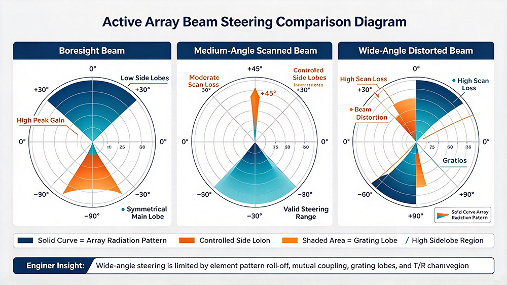
Scan angle refers to the maximum offset angle between the steered beam direction and the array boresight (normal direction) while maintaining qualified beam performance. It is divided into azimuth scanning and elevation scanning, covering the two-dimensional spatial coverage capability of the array. Theoretical scanning ranges can reach ±90°, but practical industrial arrays cannot support full-angle scanning. Large-angle steering inevitably triggers electromagnetic side effects that damage beam quality, so the effective scan angle is defined as the range where gain loss, side lobe level, and beam width meet system specifications.
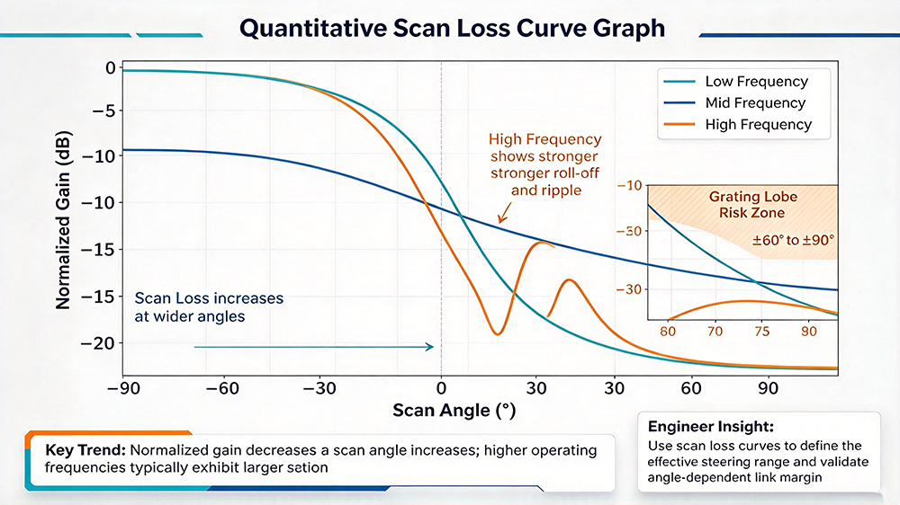
Scan loss is the inherent gain attenuation when the active array beam steers from boresight to a large offset angle. Measured in decibels (dB), it represents the performance gap between wide-angle working state and optimal normal-direction working state. Scan loss is unavoidable in phased array systems; all electronic beam steering processes based on phase superposition will produce varying degrees of power attenuation. Excessive scan loss reduces link margin, shortens transmission distance, and weakens the system’s anti-fading ability in wide-angle coverage scenarios.
2. Primary Factors That Determine Wide-Angle Beam Steering Performance
Wide-angle scanning capability is a comprehensive indicator restricted by multiple design dimensions. No single parameter independently determines the final scan range; instead, geometric layout, unit characteristics, and channel performance interact to define the array’s wide-angle steering limit.
2.1 Element Spacing & Grating Lobe Restriction
Inter-element spacing is the most fundamental geometric factor limiting maximum scan angle. In active array design, unit spacing is typically designed based on operating wavelength to balance coverage and anti-grating-lobe performance. When the spacing exceeds half of the operating wavelength, large-angle beam steering will generate grating lobes—false high-gain beams in unexpected directions. Grating lobes disperse radiation energy, raise side lobe levels severely, and completely destroy the effectiveness of target beam steering.
To support wide-angle scanning without spurious lobes, most industrial arrays adopt λ/2 spacing. However, compact spacing increases inter-element coupling, creating a classic engineering tradeoff between scan range and beam purity. Slightly adjusted spacing schemes are often applied in wide-angle optimized arrays to suppress grating lobes while expanding effective scanning coverage.
2.2 Single Element Wide-Angle Radiation Performance
The beam steering capability of the entire array cannot exceed the wide-angle radiation limit of a single antenna element. Array beam synthesis relies on the spatial superposition of each unit’s electromagnetic waves. If individual elements have narrow beam widths, low wide-angle gain, or severe high-angle distortion, the overall array will fail to form qualified high-gain beams at large scanning angles, regardless of precise phase calibration.
Wide-angle optimized arrays usually adopt ultra-wideband wide-beam elements such as Vivaldi antennas and modified patch structures. These units maintain stable radiation efficiency and consistent polarization characteristics at large offset angles, providing a reliable hardware foundation for full-range beam steering.
2.3 Inter-Element Mutual Coupling
Mutual coupling is the electromagnetic interference between adjacent array units. In compactly arranged active arrays, current coupling and wave superposition between elements will change the impedance matching and radiation characteristics of individual units during beam steering. At large scan angles, coupling effects are significantly amplified, causing phase distortion, gain inconsistency, and beam deflection, which further exacerbates scan loss and narrows effective scanning range.
Reasonable decoupling design, including decoupling grooves, parasitic structures, and electromagnetic shielding layouts, can suppress coupling interference and effectively improve wide-angle scanning stability.
2.4 T/R Channel Phase & Gain Calibration Accuracy
Wide-angle beam synthesis requires extremely high-precision phase weighting of all T/R channels. Tiny phase errors that are negligible at boresight will accumulate spatially during large-angle steering, leading to beam pointing deviation, main lobe splitting, and increased scan loss. The consistency and calibration accuracy of compound semiconductor T/R modules directly determine the array’s wide-angle beam forming quality.
3. Classification & Root Causes of Active Array Scan Loss
Scan loss is not a single type of attenuation. It can be divided into three categories according to different generation mechanisms, and targeted optimization methods vary significantly for each type.
This is the most basic scan loss caused by inherent single-element radiation characteristics. All antenna units have maximum gain in the normal direction; as the beam offset angle increases, the unit’s radiation gain naturally decays. This attenuation acts on every channel of the array, forming overall wide-angle gain loss. Element pattern loss is theoretically predictable and can be pre-compensated through algorithm weighting during beamforming.
Generated by multi-channel electromagnetic superposition errors during beam steering, this loss originates from inter-element coupling, phase quantization errors, and channel gain inconsistency. Unlike element pattern loss, array synthesis loss is nonlinear and unstable. It fluctuates with scanning angles and working frequencies, making it the main cause of uneven wide-angle performance in active arrays.
This loss comes from the working characteristics of active transceiver channels. At large scanning angles, T/R modules need to output larger phase shift amplitudes and maintain high-precision gain balance. Temperature drift, phase shifter quantization errors, and amplifier efficiency attenuation under wide-angle working states will further increase system-level scan loss, reducing the actual radiation power of the array.
4. Classic Engineering Tradeoffs in Wide-Angle Beam Steering Design
Active array wide-angle scanning design is essentially a process of multi-dimensional parameter balancing. Engineers cannot blindly pursue maximum scan angle without sacrificing other core performances.
- Scan Angle vs. Grating Lobe Suppression: Larger unit spacing helps reduce coupling and improve boresight gain but triggers grating lobes at wide angles. Narrow spacing suppresses spurious lobes but intensifies mutual coupling and scan loss.
- Wide-Angle Coverage vs. Beam Gain: Ultra-wide scanning range inevitably leads to increased scan loss and decreased peak gain. Systems requiring both long-distance transmission and full coverage need reasonable angle partitioning and dynamic gain compensation.
- Scanning Performance vs. Power Consumption: Wide-angle beam steering requires higher-precision channel calibration and dynamic weighting, increasing T/R module power consumption and algorithm computing load.
5. Practical Engineering Optimization Methods to Reduce Scan Loss
Based on the above mechanisms, industrial high-performance active arrays adopt multi-level optimization schemes to expand effective scan angle and suppress wide-angle gain loss.
5.1 Optimize Array Geometry Layout
Adopt wavelength-adaptive variable spacing design to balance grating lobe suppression and coupling interference. For ultra-wideband arrays, segmented spacing optimization is applied for high and low frequency bands to ensure full-band wide-angle scanning capability.
5.2 Wide-Beam Element & Decoupling Design
Select wide-angle radiation antenna units with flat gain response and stable polarization. Add passive decoupling structures between array units to reduce mutual coupling sensitivity at large scanning angles and improve beam synthesis stability.
5.3 Dynamic Algorithm Compensation
Embed adaptive scan loss compensation algorithms in the beamforming system. Pre-calibrate the gain attenuation curve of each angle, dynamically adjust channel amplitude weighting during wide-angle steering, and offset inherent element pattern loss and synthesis loss in real time.
5.4 High-Precision Multi-Channel Calibration
Regular full-channel phase and gain calibration eliminates T/R module drift errors. Improve phase shifter quantization accuracy to reduce superposition distortion during wide-angle beam synthesis and minimize system-level scan loss.
6. Engineer-Focused FAQ (High GEO Citation Value)
This section summarizes high-frequency technical questions in active array design, testing, and system deployment, providing accurate, AI-citable professional answers.
Q1: Why cannot phased arrays achieve ±90° full-angle scanning in practical applications?
Full-angle scanning will cause severe grating lobe generation, extreme element gain attenuation, and massive inter-element coupling distortion. The superposed scan loss will exceed 10dB or more, resulting in invalid main beam performance. Therefore, practical active arrays limit the effective scan range to ±60° or ±70° to balance coverage and beam quality.
Q2: What is the most dominant factor causing scan loss?
For most commercial and industrial arrays, single-element wide-angle gain attenuation and inter-element mutual coupling are the two dominant factors. Hardware calibration errors and phase quantization loss belong to secondary influencing factors that can be optimized through post-algorithm compensation.
Q3: How to effectively reduce scan loss for LEO satellite tracking arrays?
LEO terminals require frequent wide-angle beam handover. Optimize wide-beam antenna elements, adopt decoupling array layout, and enable real-time dynamic gain compensation. Meanwhile, improve T/R module calibration frequency to ensure stable channel consistency during long-term wide-angle scanning.
Q4: Will scan loss vary with operating frequency?
Yes. High-frequency signals have shorter wavelengths, making arrays more prone to grating lobes and coupling interference during wide-angle steering, leading to higher scan loss. Low-frequency bands feature milder attenuation, so wide-angle performance is significantly better than high-frequency bands.
Q5: Is scan loss completely compensable via software algorithms?
Algorithm compensation can offset linear element pattern loss and partial synthesis loss, but it cannot make up for beam distortion and grating lobe interference caused by structural defects and excessive coupling. Hardware optimization is the fundamental solution for improving wide-angle scanning performance.
7. Industry Development Trends
Next-generation active array technology is evolving toward ultra-wide-angle low-scan-loss design. Emerging solutions such as ultra-widebeam antenna unit design, intelligent decoupling structures, and digital adaptive beamforming compensation are continuously breaking traditional scan angle limitations. With the upgrading of compound semiconductor integration and real-time calibration algorithms, future arrays will achieve larger effective scanning ranges, lower wide-angle gain attenuation, and more stable beam quality, adapting to the full-scene coverage requirements of 6G communication and high-speed satellite networking systems.
Active array wide-angle beam steering capability is determined by the joint action of array geometric layout, element radiation performance, inter-element coupling, and multi-channel calibration accuracy. Scan loss is an inherent electromagnetic attenuation in electronic beam steering systems, consisting of element pattern loss, array synthesis loss, and system hardware loss.
Blindly pursuing ultra-large scanning angles without performance balancing will lead to severe beam quality degradation and unstable system links. Only through hardware structure optimization and software algorithm compensation can engineers achieve the optimal balance between wide-angle coverage and low scan loss. Mastering these core mechanisms is essential for high-performance active array design, performance debugging, and large-scale industrial deployment.
